
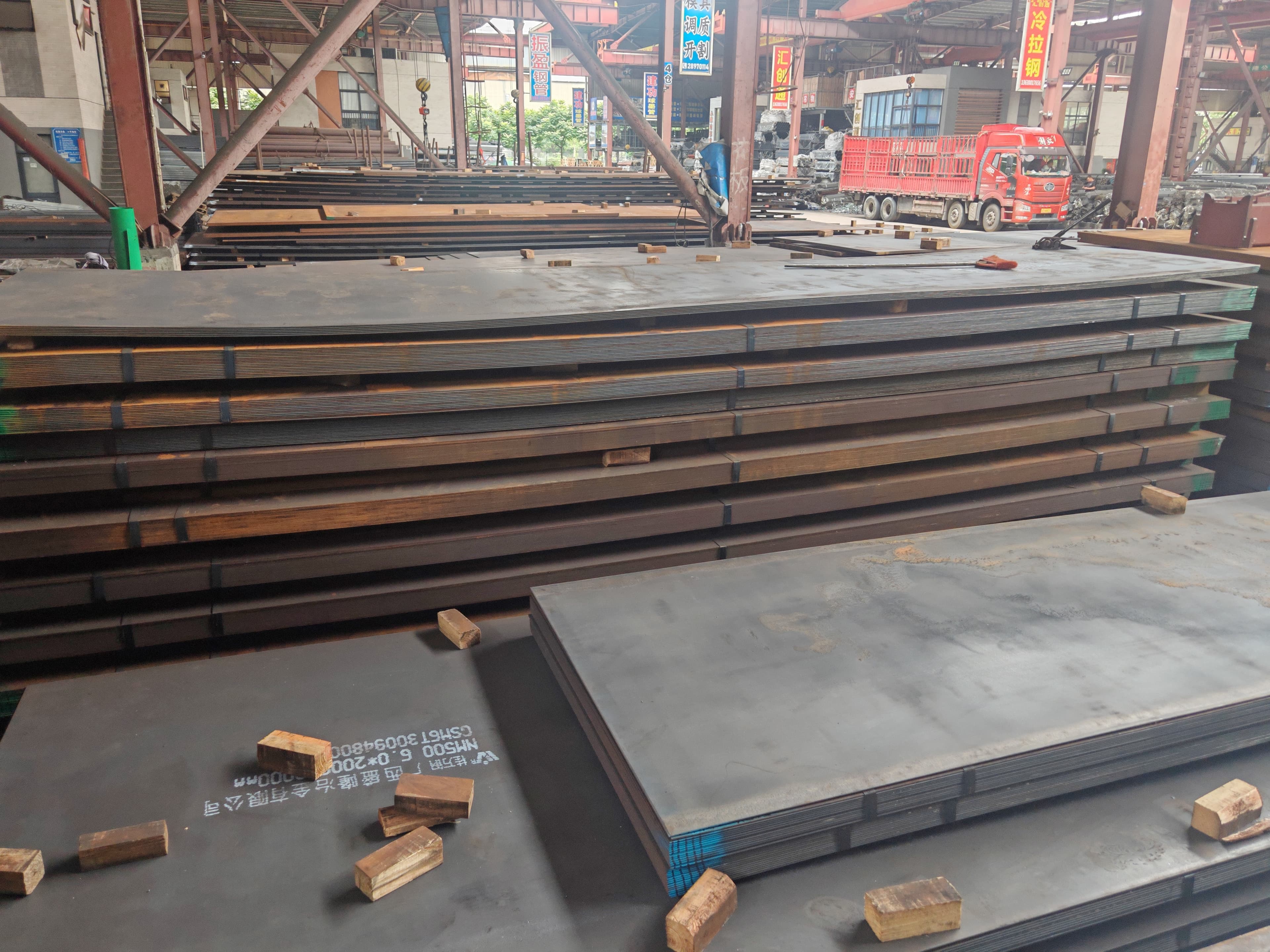
Select chute and hopper wear plate by mapping the equipment into impact, transition and sliding zones. Record particle size, hardness, moisture, velocity and drop height; then balance plate hardness with toughness, support, attachment and workshop capability. NM450–NM500 are common starting candidates, while NM550–NM600 require controlled impact and fabrication review. Validate the choice with inspection and measured wear data.
ZGT Steel is an independent trading and export company, not an owned steel mill. Product guarantees depend on the approved producer and order specification. Application guidance is for initial selection and does not replace engineering approval.
Treat the chute as a wear system, not a single steel grade
A chute can fail even when the liner material is hard. Concentrated impact, poor flow control, unsupported spans, trapped material, loose fasteners and abrupt geometry can dominate the wear rate. The correct question is therefore not simply “Which plate is hardest?” but “Where and how is energy entering the liner?”
Divide the equipment into zones. The impact zone receives falling lumps and usually needs toughness, support and energy management. The transition zone changes flow direction and can experience gouging. The sliding zone sees sustained abrasive movement, where higher hardness may offer more benefit. Dead zones can trap material and create corrosion or unpredictable flow.
Walk-down observations are valuable. Record polished areas, grooves, dents, cracks, bolt movement, worn welds and material buildup. Compare left and right sides and review the feed distribution. These patterns reveal whether the dominant problem is abrasion, impact, attachment or flow design.
The application data a supplier needs
Describe the handled material: ore or aggregate type, maximum and typical particle size, angularity, bulk density, moisture and contaminating fines. If laboratory mineral hardness is available, include it, but do not assume that a single number predicts the entire wear system.
Provide operating data such as throughput, belt speed, drop height, impact angle, operating hours and temperature. Intermittent surges can be more damaging than average flow. Note whether the equipment is mobile or stationary and whether vibration or structural movement affects the liner.
Send drawings and site photographs with dimensions. Identify current liner grade and thickness, installation date, measured remaining thickness and failure location. Customer requirements for maintenance interval, maximum piece weight and available lifting equipment influence the part layout as much as material selection.
- Material, particle size, moisture and angularity
- Throughput, velocity, drop height and angle
- Current grade, thickness and observed failure
- Support structure, attachment and access
- Target maintenance interval and shutdown window
Matching hardness and toughness to each wear zone
For impact zones, a lower or mid-range hardness class with verified toughness may be safer than an extreme-hardness plate selected only for abrasion. NM400 or NM450 can be starting candidates where large lumps strike the liner, but the exact product specification, temperature and support must be reviewed.
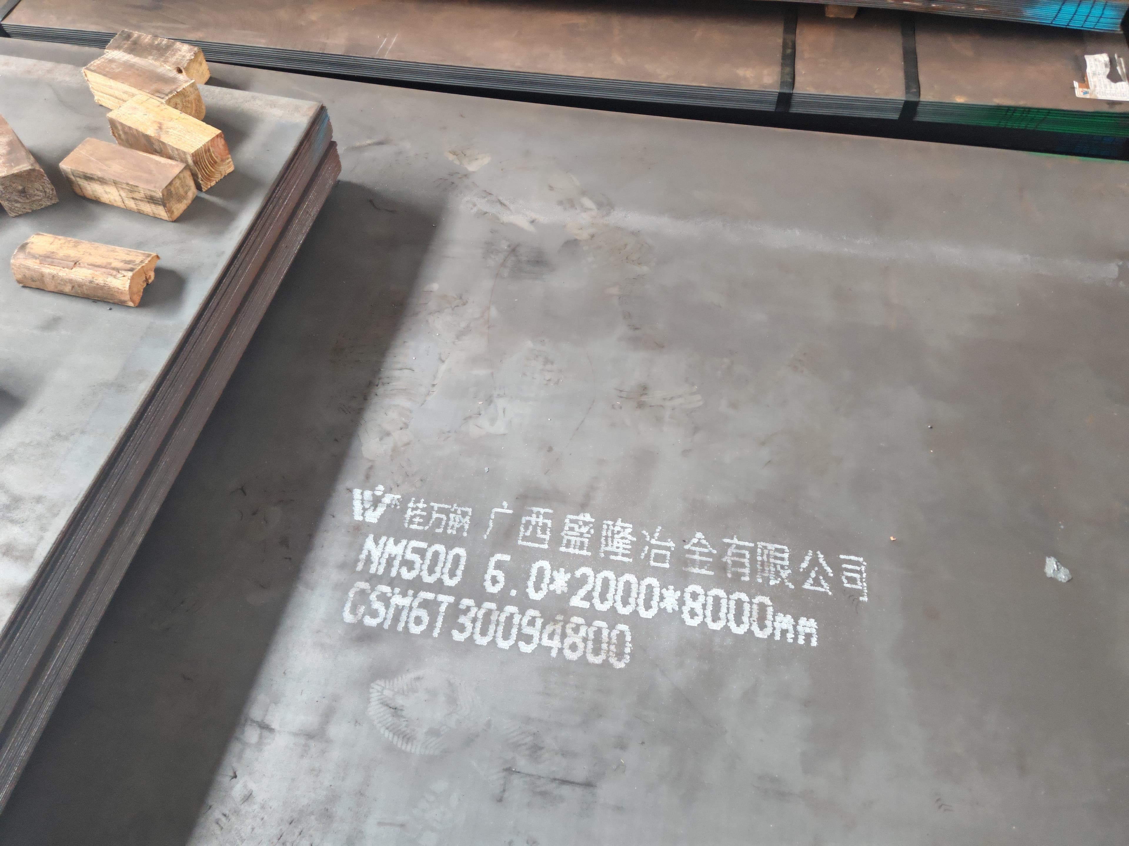
For sliding zones with moderate impact, NM450 and NM500 are common candidates. Higher hardness can reduce penetration by abrasive particles, while the design must still allow reliable cutting, drilling and attachment. NM500 may suit replaceable flat liners when the workshop follows the specific fabrication guideline.
NM550 and NM600 can be considered for high-abrasion, controlled-impact areas and relatively simple parts. Availability, thickness, flatness, holemaking and welding procedures need early review. In severe impact, adding hardness without addressing energy and support can move the failure from gradual thinning to cracking.
Metallic plate is not the only option. Ceramic, rubber, polyurethane, overlay plate or hybrid liners can be relevant depending on impact, temperature, particle size and maintenance. The purpose of a zone map is to allow different solutions where the physics differs.
Liner design decisions that strongly affect service life
Support the liner so it does not repeatedly flex under impact. Check the backing structure for corrosion, distortion and gaps. A hard plate on a weak support can crack or loosen even when the material itself meets specification.
Choose manageable liner sizes. Very large panels reduce joint count but can be difficult to handle and may accumulate distortion. Smaller modular liners simplify replacement but add fasteners and joints. The best layout balances installation access, lifting capacity, wear pattern and inventory.
Avoid placing joints, bolt heads or weld terminations at the point of maximum impact when possible. Protect exposed fasteners from direct flow and allow worn liners to be removed safely. Where plug welding or perimeter welding is proposed, review restraint, heat input and replacement method.
Flow-control features such as rock boxes or ledges can create a material-on-material layer that reduces direct contact. Their suitability depends on flow stability and blockage risk. A design review may deliver more improvement than changing from one hardness grade to the next.
Fabrication and installation preparation
Create a drawing package that identifies each liner, material, thickness, hole pattern, orientation and marking. Confirm whether holes are drilled, machined or thermally cut and what tolerance applies. Tight hole-position requirements may justify final machining after cutting.
Follow the selected producer’s instructions for thermal cutting, bending and welding. Plate temperature, thickness, carbon equivalent, hydrogen control and restraint affect the procedure. Remove cutting defects and inspect bend edges or weld areas according to the agreed quality plan.
Trial-fit assemblies where practical. Check bolt accessibility, countersink seating, overlap direction and interference with neighboring components. Mark every part so the installation crew can match it to the layout drawing. Pack replacement sets in installation sequence when site time is limited.
Build a wear-monitoring plan before startup
Record the as-installed thickness at fixed measurement points. Use a numbered diagram or digital model so later readings are taken in the same locations. Note commissioning date, operating hours and tonnage handled.
Inspect early enough to catch unexpected localized wear. The first interval should be conservative, then adjusted once the wear rate becomes clear. Ultrasonic thickness measurement can support monitoring when surface and access conditions permit, but the method and calibration should be appropriate.
Normalize results by tonnage or operating hours and record changes in feed. When comparing two grades, install them in genuinely comparable positions or alternate sides if the flow is symmetrical. A small, controlled field trial produces better purchasing evidence than a generic claim that one plate lasts a fixed multiple longer.
From site problem to a purchase-ready specification
A useful request includes the zone map, drawings, current wear history, proposed materials, processing scope and inspection requirements. Ask the supplier to identify assumptions and technical exceptions. If an equivalent grade is offered, request the producer datasheet and a clear comparison of guaranteed values.
For finished liners, agree dimensional reports, material traceability, part marking, packing by equipment area and shipment photographs. Installation preparation should be checked before release because a technically correct material can still cause downtime if the parts arrive mixed or unidentified.
Treat the first order as part of an improvement cycle. Review field performance with operations and maintenance, then update grade, thickness, liner geometry or attachment. The objective is reliable cost per tonne handled—not the highest hardness number on the quotation.
Use failure evidence to improve the next liner set
When a liner is removed, preserve more information than a single photograph. Mark its orientation, measure the remaining thickness on a grid and record cracks, deformation, hole elongation, worn welds and localized grooves. Note total operating hours, tonnes handled and any change in ore source or moisture.
Smooth, broadly distributed thinning suggests abrasion is controlling. Deep grooves can indicate large angular particles or a concentrated stream. Dents and plastic deformation point toward impact energy or inadequate support. Cracks may relate to impact, restraint, cut-edge quality, welding, temperature or material choice. Several mechanisms often appear together.
Compare the damaged liner with the backing structure. Gaps, corrosion, loose bolts and distorted supports can cause movement that no grade upgrade will solve. Check whether neighboring liners transferred load correctly and whether fastener protection remained intact.
For the next trial, change one major variable where possible. Moving from NM450 to NM500 while also changing thickness, geometry and feed conditions makes the result difficult to interpret. A controlled comparison should use similar positions and record the same measurement points.
Share the evidence with the material and processing supplier. Useful feedback includes the zone drawing, measurement table, operating record and installation notes. This enables a more specific recommendation and helps define which values or inspections should be added to the next purchase order.
Turn the application into a verifiable specification.
The best wear-plate decision connects operating conditions, material guarantees, processing, inspection and installation. Use the framework above to create a clearer RFQ, compare proposals on the same basis and build field evidence after installation. Avoid universal service-life promises; measurable requirements and traceable records create a more dependable result.
Buyer questions, answered clearly.
Often, especially in sliding-abrasion zones, but suitability depends on impact, support, temperature, fabrication and the exact product specification. Review the chute by zone.
Technical references
These sources support the general grade and fabrication framework. Contractual values must come from the producer documentation for the offered material.
SSAB overview of wear mechanisms and grade categoriesJFE EVERHARD applications and grade ranges
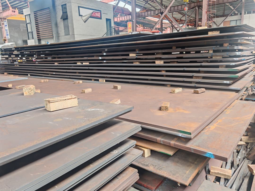 NM400 vs NM450 vs NM500 wear plate
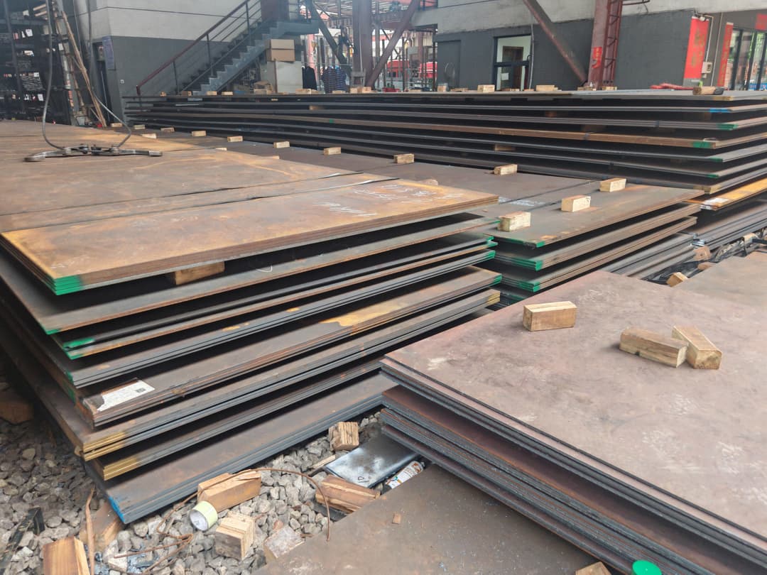 wear resistant steel plate inspection checklist